Rectifier is a device which converts alternating current (AC) to direct current (DC). Half wave and full wave rectifiers are used in rectifying AC signal. AC signals have both positive and negative directions but DC signal has only one direction. The power line transmits AC power but most of the appliances require DC power. The function of rectifier is not understood by simply explaining it but it needs to know about transformer and filter circuits.
High AC voltage is first reduced to required level AC voltage using stepdown transformer. Then, circuit that contains diodes, is known as rectifier circuits. Half wave rectifier has only one diode and center tapped full wave rectifier consists of two diodes. Full wave bridge rectifier has four diodes. For instance, center tapped design can be taken to explain the function of rectifier.
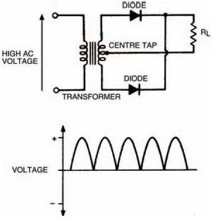
Reduced AC voltage is appiled to diode circuits. During First half of cycle (positive), top diode only conducts because voltage polarity is +ve on top and -ve on bottom. Now output sees voltage in positive direction. During second half of cycle (negative), AC polarity is reversed. Now bottom diode conducts but top diode does not conduct. The output again sees voltage in positive direction.
In output, pure DC voltage can not be expected because rectifier gives output in positive directions but in same wave format. To remove waviness, filter circuit is needed after recifier circuit. A capacitor can be used after rectifier circuit and it removes waviness of output from rectifier. However, some ripples are present in output. To avoid ripples, regulator circuits are used followed filter circuit.